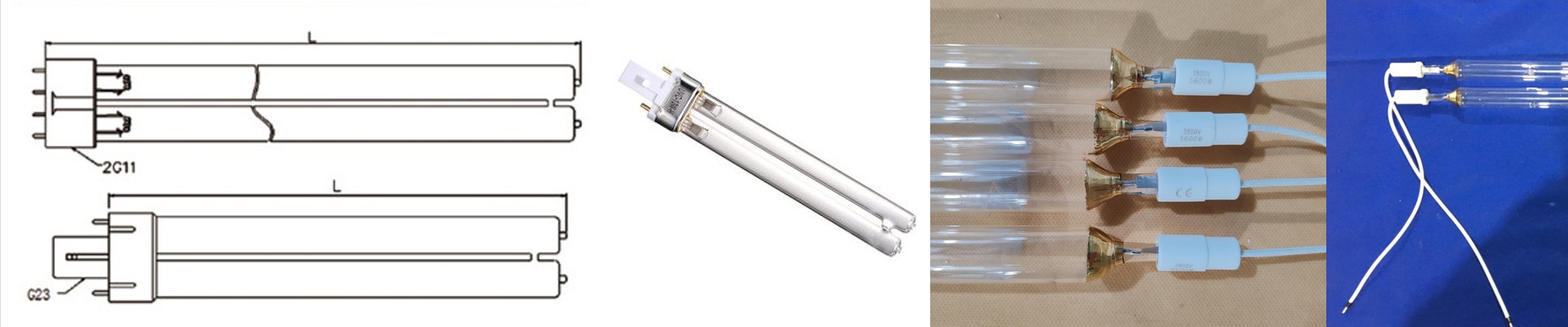
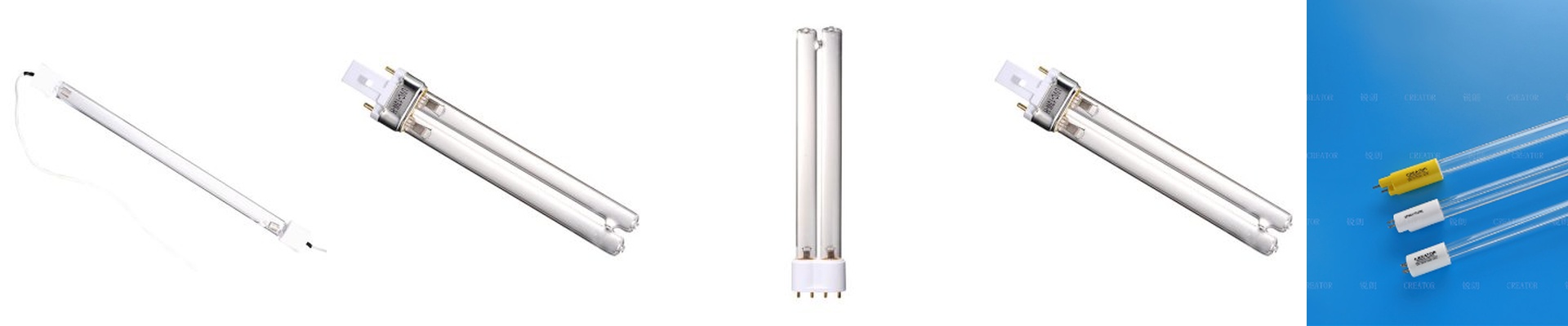
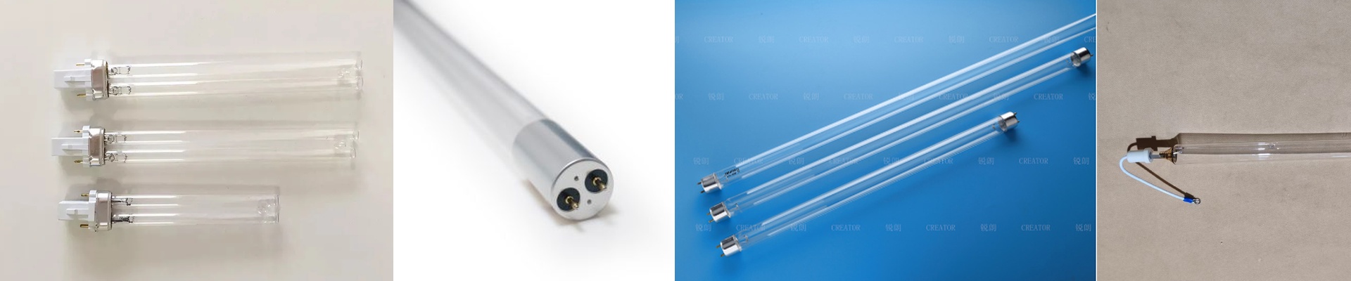
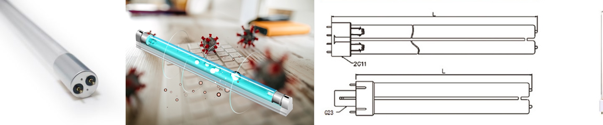
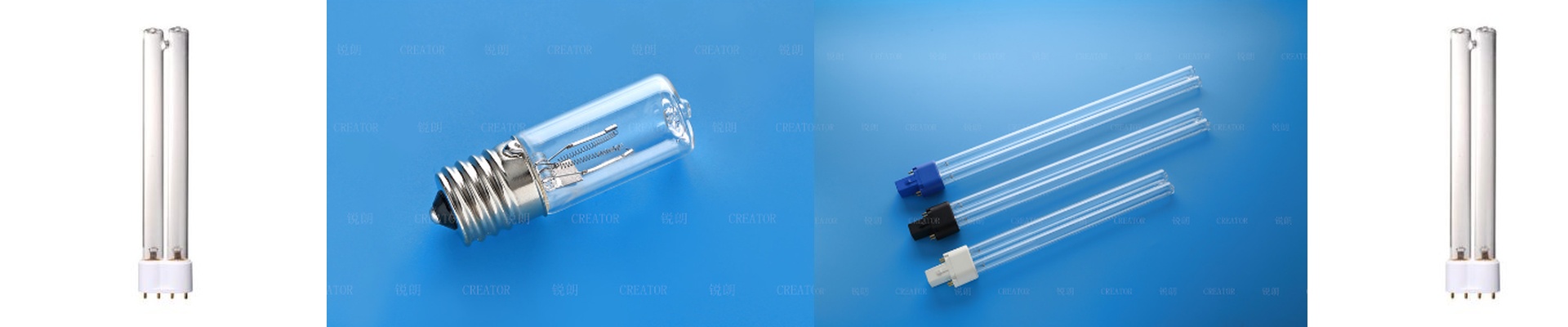
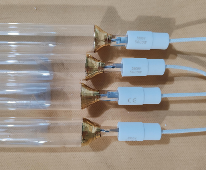
On the press, complex and contoured substrates routinely beat standard UV setups. Shadowed areas—where reflector geometry and lamp placement just can’t reach—stay tacky, and that means scrap and rework. The real question isn’t whether UV energy hits the surface. It’s whether the spectral profile and spatial distribution get deep into recesses without blowing out the peaks.
What matters, technically
Gallium-doped UV emitters push the spectral output toward 395–405 nm, which lines up with thick-film photoinitiators and gives photons better penetration. Compared with mercury-dominant lines at 365 nm, the 405 nm peak yields more uniform through-cure in pigmented and filled formulations, so the gradient between surface and bottom layers shrinks. We call out peak irradiance at the substrate plane in mW/cm², and we hold stable output over 5,000+ hours with less than 5% drop. Reflectors use dichroic coatings tuned to the gallium profile, focusing usable UV while keeping IR heat off the substrate. Ozone-free operation is standard, and the emitter fits into compact arrays with defined hot-spot mapping, so you can predict energy density (mJ/cm²) across the print window.
Why it works in the real world
We build customized UV heating elements around gallium emitters to reshape the energy field, so contours no longer create dead zones. By controlling beam divergence and adding secondary micro-reflectors, we drive curing flux into undercuts and along edges—no more shadows stalling production on irregular parts. The payoff is repeatable cross-linking across the whole print, not just on the flats. You get consistent cure at line speed, fewer rejects, and fewer lamp changes. Energy use drops because the system hits the required dose at the substrate without over-lamping.
The practical details
Gallium emitters demand tight thermal management. Keep an eye on substrate temperature—reflector efficiency can drive local heat. Before integration, confirm fixture compatibility and reflector geometry; output uniformity hinges on precise alignment to the print path. And plan for spectral verification with a calibrated radiometer at the substrate plane, not at the lamp face.